This has been updated after some feedback that I received from a more experienced FPGA designer explaining that asynchronous reset is an inappropriate default approach because it can cause partial resets, metastability, and partially correct computations as it moves across the device. Therefore, a synchronous reset should be expected, with a dedicated reset synchronizer (not shown or considered here)
Last time I wrote about how to organize a basic Verilog module that implements a combinational circuit in order to improve clarity for readers and synthesis tools alike. Implementing a sequential circuit correctly is a lot more challenging because it requires an internal combinational circuit. For my discussion I will largely focus on Altera's tools, because they are what I use on a day-to-day basis, but I would expect the same principles to apply to code targeting Xilinx or another vendor.
The traditional approach to designing a sequential circuit begins by creating a state diagram. In a classroom setting, students would then go on to pick a state encoding, create transition tables, and then optimize the combinational logic for implementation. Luckily, as an engineer I don't have to do things the academic way, and I can instead rely on the synthesis tools to optimize the combinational circuit for me. With a good set of tools, it is actually possible for the synthesis step to choose a better state encoding (to minimize logic usage, propagation delay, or register usage, as necessary) than one that I will choose arbitrarily, which means that I can focus primarily on making sure the transition and output logic is correct. Frequently, I don't even create a state diagram on paper, instead setting up the template that I normally use and then writing in the state transitions directly while defining the state machine's behavior.
With that as the goal, a specific approach to writing state machines is necessary to ensure that it's clear to the synthesis tools and to other readers what is going on. There are two options: one is to use a graphical state machine builder, which I would obviously prefer not to do, as Verilog is usually faster to write and easier to maintain, because clicking is not an efficient way to transfer input to the computer (at least, not as efficient as the keyboard, in this case). The other option is to use language features to alert the synthesis tools that you are creating a state machine. In Quartus II, this can be done using the parameter data type to create state variable templates, or, alternatively, I prefer using the `define keyword to define states as constants. Both will be picked up by the synthesis tools and allow for state remapping if desired. Although Altera recommends using parameter, I prefer the use of `define because it does not expose the state variables to the hierarchy as modifiable in the way a module parameter does. Note however that the Altera tools compile all the files in a shared namespace, so all `define'd symbols must have unique names. This is easy to do with a consistent naming scheme, personally I use STATE_<MOD>_<STATE NAME>, with MOD being up to 5 letters of abbreviation for the module being implemented.
One important behavior to note here is that Altera has different options for state machine synthesis, some of which increase the number of bits used for state encoding (such as one-hot encoding). Therefore, it may not always be a good thing for the synthesis tools to infer a state machine—if explicit structural storage is instantiated (such as lpm_ff) then the state machine will not be optimized by the compiler. The state machine can also be specifically set to use "user-defined" encoding by placing a synthesis directive on the same line as the state variable's declaration. All of the options for state machine encoding are specified in this document describing Quartus II Synthesis options.
(* syn_encoding = "user" *) reg [1:0] state;
Structurally, it is important to separate storage logic from state calculation logic, for a couple of reasons. First, the prevailing belief is that blocking assignments (with the = operator) should be used for combinational logic only, while non-blocking assignments (with the <= operator) should be used for sequential logic only. Assignment types should never be mixed within a single behavioral block because unintended or unpredictable simulation and synthesis behavior can result from differences in interpretation. Therefore, use non-blocking assignment in an edge-sensitive behavioral block to implement the storage logic, and use blocking assignment in a combinational behavioral block to implement next state and output.
Second, it makes the module easier to maintain if the its organization reflects the hardware structures that it is implementing, and it is more likely for the synthesis tools to produce the most optimal implementation. In particular, when dealing with enable, synchronous or asynchronous preset or clear signals, and other features normally associated with the flip flop elements themselves (as opposed to a part of the combinational logic before the flip flop), on a modern FPGA these features can either be implemented as logic inside the LUTs or they can be implemented using the dedicated enable, preset, and clear lines of the storage element within the LE. In order to make it clear to the tools that an enable is being used, the conditional use of the enable should be in the storage block, not the combinational block. For example, consider the following two implementations of a simple vending machine that accepts two coin types (1 and 2, where coin 2 is worth two of coin 1) and counts up to a total of three of coin 1. Then it issues a vend signal and returns to the idle state, with no change calculations, for simplicity.
/** Implementation A */
assign vend = (state == `STATE_EX_S3);

always @* begin
    nextState = state;

    case(state)
        `STATE_EX_IDLE : begin
            if (coin1 == 1'b1) begin
                if (enable == 1'b1)
                    nextState = `STATE_EX_S1;
            end
            else if (coin2 == 1'b1) begin
                if (enable == 1'b1)
                    nextState = `STATE_EX_S2;
            end
        end
        `STATE_EX_S1 : begin
            if (coin1 == 1'b1) begin
                if (enable == 1'b1)
                    nextState = `STATE_EX_S3;
            end
            else if (coin2 == 1'b1) begin
                if (enable == 1'b1)
                    nextState = `STATE_EX_S3;
            end
        end
        `STATE_EX_S2 : begin
            if (coin1 == 1'b1) begin
                if (enable == 1'b1)
                    nextState = `STATE_EX_S3;
            end
            else if (coin2 == 1'b1) begin
                if (enable == 1'b1)
                    nextState = `STATE_EX_S3;
            end
        end
        `STATE_EX_S3 :  begin
            if (enable == 1'b1)
                nextState = `STATE_EX_IDLE;
        end
    endcase
end

always @(posedge clk) begin
    if (reset_L == 1'b0) begin
        state <= `STATE_EX_IDLE;
    end
    else begin
        state <= nextState;
    end
end
/** Implementation B */
assign vend = (state == `STATE_EX_S3);

always @* begin
    nextState = state;

    case(state)
        `STATE_EX_IDLE : begin
            if (coin1 == 1'b1) begin
                nextState = `STATE_EX_S1;
            end
            else if (coin2 == 1'b1) begin
                nextState = `STATE_EX_S2;
            end
        end
        `STATE_EX_S1 : begin
            if (coin1 == 1'b1) begin
                nextState = `STATE_EX_S3;
            end
            else if (coin2 == 1'b1) begin
                nextState = `STATE_EX_S3;
            end
        end
        `STATE_EX_S2 : begin
            if (coin1 == 1'b1) begin
                nextState = `STATE_EX_S3;
            end
            else if (coin2 == 1'b1) begin
                nextState = `STATE_EX_S3;
            end
        end
        `STATE_EX_S3 :  begin
            nextState = `STATE_EX_IDLE;
        end
    endcase
end

always @(posedge clk) begin
    if (reset_L == 1'b0) begin
        state <= `STATE_EX_IDLE;
    end
    else if (enable == 1'b1) begin
        state <= nextState;
    end
end
When I synthesize both of these files, I would normally expect the same result as they are logically equivalent. However, because the default assignment of nextState is not gated by the enable signal while all of the state transitions are, the synthesis tools are unable to push the enable condition through up to the register, and implementation A requires two LEs more than implementation B. Unfortunately, due to the state machine inference there are further problems: the enable signal is inferred as a part of the state transitions (technically, it is, although not many think about it that way because it affects all of state transitions in the same way). If I simply replace the behaviorally generated flip flop with an explicit structural D-Flip Flop using the Altera primitives, the same relationship exists (A requires two more LEs than implementation B), but both implementations require two fewer LEs overall:
/** Implementation A */
lpm_ff #(.lpm_width(2)) storage(.clock(clk), .sclr(!reset_L), .data(nextState), .q(state));

/** Implementation B */
lpm_ff #(.lpm_width(2)) storage(.clock(clk), .sclr(!reset_L), .data(nextState), .q(state), .enable(enable));
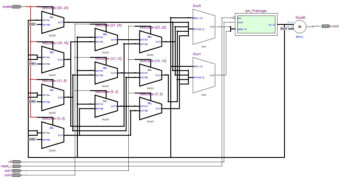
A quick look at the RTL Viewer shows that the discrepancy between implementations A and B is due to the enable signal not being pushed into the flip flops and instead being implemented in logic.
vs.
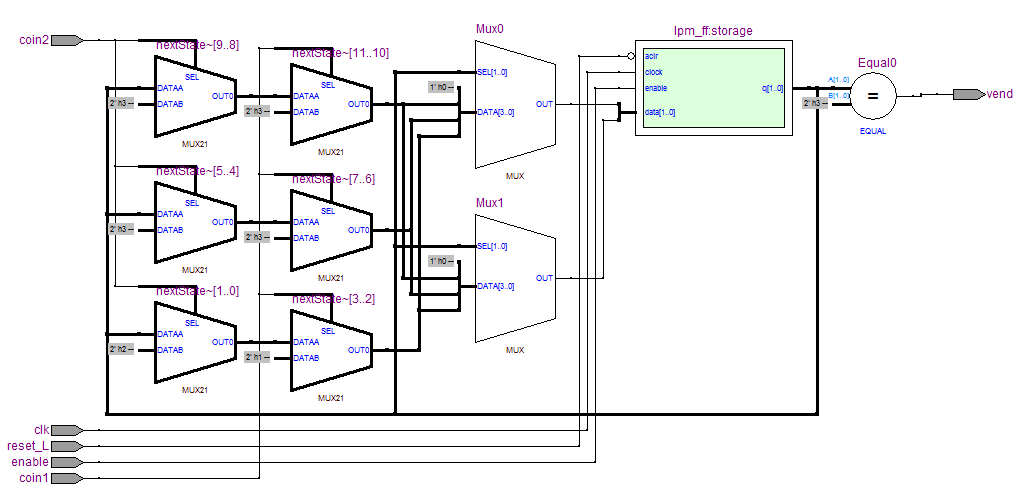
We can see that the same six multiplexers (more or less) are used to implement the state transition logic, but for implementation A, the enable signal is being handled purely in logic before the state transition logic, whereas in implementation B it is correctly passed off to the enable signal on the D Flip Flop that is already available in the LE's register, with no additional logic cost. As a result, be sure to separate signals that are (or can be) associated with the storage elements themselves and handle them near the storage element, either inside the appropriate sequential behavioral block or with the appropriate input on the structural storage element, rather than in with the rest of the next state logic. This is both cleaner to read and understand and it will generally produce better synthesis results.
Third, and last for now, on the list of file organization techniques is the use of the case statement (or its relatives, casex and casez) inside the combinational block for next-state logic, unless building a counter or other type of state machine where the state transitions are systematic, in which case simple statements like nextState = state + 1'b1; are sufficient. If a counter is being used inside another state machine to determine timing, then I believe it is sufficient to increment the counter as a default option and reset or modify it as necessary in the actual states that have logic governing their progression. While examining the earlier vending machine example, when the resource usage was significantly higher than expected, I found that if the vend signal was assigned inside the combinational block and the state-handling logic was an if-else if tree, three unnecessary multiplexers were generated to drive the output, although the state machine logic was still calculated correctly. If, instead, the case structure were used or the continuous assignment that I finally settled for (in keeping with my guidelines for combinational logic—it was simple enough to be stated as continuous assignment, therefore it should be handled that way), then the multiplexers did not appear. I believe this is due to a difference in representation for if-else trees and case statements internal to the synthesis tools, and because the case structure is arguably more reasonable in one's source code because behavior must be defined for every state, more or less, the tools handle it much better.
A potential fourth rule that some people would advocate is physically separating the logic for calculating the next state and the logic for calculating the machine outputs into two behavioral blocks, but I make no recommendation here. For Moore-type machines, this can be reasonable because it provides visual clues as to what each block corresponds to on the typical mental image that most people have for a Moore-type machine (input -> combinational logic -> flip flops -> output logic -> outputs), but personally I find that this just leads to more coding (or copy/pasting the case structure) with no significant benefit. I also use primarily Mealy-type machines, where the separation argument doesn't make much sense, because the outputs will also depend on the input. As a result the two blocks would end up mirroring each other very closely in a structural sense, and, without the correct set of tool options, the synthesizer could generate two copies of the control/condition signals for the relevant multiplexers, wasting resources. I haven't had the opportunity (read: desire) to explore possible differences in synthesis for the two approaches, so I cannot provide definitive advice on which style is better.
Finally, with these three (four?) rules in mind, I present a general Verilog state machine template based on the guidelines described above. I also realized that it was more useful to provide this as a copy/paste-able fill-in-the-blanks template, rather than one with dummy logic already present. Plus, the earlier vending machine implementations also exemplify this, just without the description of what goes where.
// Verilog state machine template
module state_proto(clk, reset_L, ...);
    input clk;
    input reset_L;
    // ... other inputs/outputs

    // State declarations
    `define STATE_EX_S0     2'b00
    `define STATE_EX_S1     2'b01

    // State variables
    reg [1:0] state;
    reg [1:0] nextState;
    // ... more state variables for embedded state machines

    // ... Internal signals/wires

    // Continuous time assignment for simple outputs and internal signals

    // Next state and output logic
    always @* begin
        nextState = state;
        // ... default values for outputs and other state machines

        case (state)
            `STATE_EX_S0 : // ... transition logic/output logic
            `STATE_EX_S1 : // ... transition logic/output logic
            // ... more states
        endcase
    end

    // Storage, combine all state machine storage, with synchronous clear
    always @(posedge clk) begin
        if (reset_L == 1'b0) begin
            state <= `STATE_EX_S0;
            // ... other state defaults
        end
        else begin
            state <= nextState;
            // ... flop in other storage unconditionally
        end
    end

    // Structural storage, instantiate things like shift registers, FIFOs, etc. Control signals
    // are generated above
endmodule