One of the most useful things that didn't come up enough in college was a very basic concept, central to almost any digital communications system: the numerically controlled oscillator (NCO), the digital counterpart to an analog oscillator. They are used in software defined radio in order to implement modulators/demodulators and they have a number of other applications in signal processing, such as arbitrary waveform synthesis and precise control for phased array radar or sonar systems. Noise performance in digital systems can be carefully controlled by adjusting the data type's precision, whereas in analog systems, even if the circuit is designed to produce a minimum of intrinsic noise, external sources can contribute an uncontrolled amount of noise that is much more challenging to manage properly. As digital systems increase in speed, analog circuits will be reduced to minimal front ends for a set of high speed ADCs and DACs.
Luckily, NCOs are easy to understand intuitively (but surprisingly difficult to explain
conceptually), which is probably why they weren't covered in-depth in school, although they are
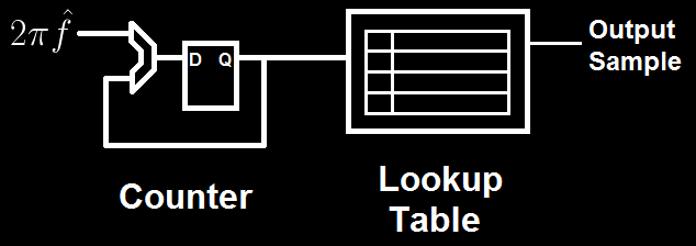
usually not immediately obvious to someone who hasn't already seen them. A basic NCO consists of a
lookup table containing waveform data (usually a sinusoid) for exactly one period and a counter for
indexing into the table. The rate of change of the counter determines the frequency of the output
wave, in normalized units, because the output wave still exists in the discrete time domain. The
counter is generally referred to as a 'phase accumulator,' or simply an accumulator, because it
stores the current value of the sine's phase, and the amount that it changes every cycle I normally
refer to as the 'phase.' In this sense, one of the simplest explanations of how an NCO works is that
it tracks the argument to ") in a counter and uses a look up table to
calculate the corresponding value of . The challenge, however, lies
in the implementation.
in a counter and uses a look up table to
calculate the corresponding value of . The challenge, however, lies
in the implementation.
Floating point hardware is expensive in terms of area and power. Software emulation of floating point is expensive in terms of time. And, of course, floating point numbers cannot be used to index into an array without an intermediate conversion process, which can consume a large number of cycles without dedicated hardware. As a result, most NCOs are implemented using fixed point arithmetic for the phase accumulator, even if the table stores floating point values for high end DSPs. Fixed point introduces the notion of "normalization" because the number of bits dedicated to integer and fractional values is fixed, limiting the numbers that can be represented. Ideally, the full range of the fixed point type is mapped to the full range of values to be represented by a multiplicative constant. In the case of NCOs, this is usually done by using a new set of units (as opposed to radians or degrees) to represent phase angle, based on the lookup table size.
Normally, the period of ") is
is  . However, for a lookup table, the period is the length of
the table, because the input is an integer index, and the table's range spans a single cycle of
. Because the index must wrap to zero after passing the end of the table, it is convenient
to choose a table size that is a power of 2 so that wrap around can be implemented with a single
bitwise operation or exploit the overflow properties of the underlying hardware for free, rather
than an if-statement, which generally requires more cycles or hardware to evaluate. Thus, for a
B-bit index, the table contains
. However, for a lookup table, the period is the length of
the table, because the input is an integer index, and the table's range spans a single cycle of
. Because the index must wrap to zero after passing the end of the table, it is convenient
to choose a table size that is a power of 2 so that wrap around can be implemented with a single
bitwise operation or exploit the overflow properties of the underlying hardware for free, rather
than an if-statement, which generally requires more cycles or hardware to evaluate. Thus, for a
B-bit index, the table contains  entries, and the possible frequencies that can be generated
are integer multiples of
entries, and the possible frequencies that can be generated
are integer multiples of  (the minimum change in the accumulator's value is naturally
one table entry).
(the minimum change in the accumulator's value is naturally
one table entry).
There is, of course, a clear problem with this implementation when precise frequency control is necessary, such as in all of the applications I mentioned at the start. If I wanted to build a digital AM radio tuner, then my sampling frequency would theoretically need to be at least 3.3 MHz to cover the entire medium wave band, where most commercial AM stations exist (although in practice it would need to be much higher in order to improve performance). If I use a table with B=8, then my frequency resolution is 0.00390625 * 3.3 MHz = 12.89 kHz, which is insufficient to form a software demodulator because the intra-station spacing is only 10 kHz. However, because the table size grows exponentially with B, it is undesirable or impossible to increase B past a certain point, depending on the amount of memory available for the lookup table. Depending on the size of the data stored in the table, there are also noise floor issues that affect the utility of increasing B, but I will discuss the effects of word size and quantization error on NCO performance another time.
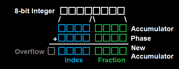
A better solution is to produce non-integer multiples of the fundamental frequency by changing the index step size dynamically. For instance, by advancing the phase accumulator by an alternating pattern of 1 and then 2 samples, the effective frequency of the output sinusoid is halfway between the frequency for 1 sample and the frequency for 2 samples, plus some noise. This makes use of a second, fractional counter that periodically increments the primary index counter. The easiest way to implement this is to simply concatenate the B-bit index with an F-bit fractional index to form a fixed point word, so that an overflow from the fractional index will automatically increment the real table index. Then, when performing table lookup, the combined fixed point word is quantized to an integer value by removing the fractional bits. More advanced NCOs can use these fractional bits to improve performance by rounding or interpolating between samples in the table. Generally, because the value of F does not affect the size of the table, but it does increase the possible frequency resolution, I find the minimum value for F to give the desired resolution and then round up to the next multiple of 8 for B+F (8, 16, 24, …). It is possible to implement odd size arithmetic (such as 27 bits), but almost always the code will require at least the use of primitives for working with the smallest supported word size, which means that there is no performance penalty for increasing F so that B+F changes from 27 to 32.
By adding the F-bit fractional index, the frequency resolution improves to integer multiples of
 , with no change in storage requirements, allowing. The only challenge, then, is
converting between a floating point normalized frequency in Hz and the corresponding fixed point
representation in table units. This is normally only done once during initialization, so the penalty
of emulating floating point can be ignored, as the code that runs inside a tight processing loop
will only use fast fixed point hardware. Because normalized frequency (in Hz) is already constrained
to the interval [0, 1), the conversion from Hz (f) to table units (p) is a simple ratio:
, with no change in storage requirements, allowing. The only challenge, then, is
converting between a floating point normalized frequency in Hz and the corresponding fixed point
representation in table units. This is normally only done once during initialization, so the penalty
of emulating floating point can be ignored, as the code that runs inside a tight processing loop
will only use fast fixed point hardware. Because normalized frequency (in Hz) is already constrained
to the interval [0, 1), the conversion from Hz (f) to table units (p) is a simple ratio:


If any fractional index bits are used, then they must be included before p is cast from a floating
point value to an integer by multiplying the value by the normalization constant,  , which is
efficiently calculated with a left shift by F bits. The resulting value is then stored as an integer
type; normally I use unsigned integers because I only need to work with positive frequency. All
subsequent fixed point operations are done using the standard integer primitives with the
understanding that the "true" value of the integer being manipulated is actually the stored value
divided by . This becomes important if two fixed point values are multiplied together, because
the result will implicitly be multiplied by the normalization constant twice and need to be
renormalized before it can be used with other fixed point value. In order to use the fixed point
phase accumulator to index into the table, the integer portion must be extracted first, which is
done by dividing by the . Luckily, this can be computed efficiently with a right shift by F
bits.
, which is
efficiently calculated with a left shift by F bits. The resulting value is then stored as an integer
type; normally I use unsigned integers because I only need to work with positive frequency. All
subsequent fixed point operations are done using the standard integer primitives with the
understanding that the "true" value of the integer being manipulated is actually the stored value
divided by . This becomes important if two fixed point values are multiplied together, because
the result will implicitly be multiplied by the normalization constant twice and need to be
renormalized before it can be used with other fixed point value. In order to use the fixed point
phase accumulator to index into the table, the integer portion must be extracted first, which is
done by dividing by the . Luckily, this can be computed efficiently with a right shift by F
bits.
In conclusion, because an NCO requires between 10 and 20 lines of C to implement, I've created a sample NCO that uses an 8.24 fixed point format with a lookup table that has 256 entries, to better illustrate the concept. The output is an integer waveform with values from 1 to 255, representing a sine wave with amplitude 127 that is offset by 128, which would normally be used with an 8-bit unipolar voltage output DAC to produce an analog signal biased around a half-scale virtual ground. This code was tested with Visual Studio 2005, but it should be portable to any microcontroller that has correct support for 32-bit types and 32-bit floating point numbers.
uint8_t sintable32[256];

struct nco32 {
    uint32_t accumulator;
    uint32_t phase;
    uint8_t value;
};

void sintable32_init(void);
void nco_init32(struct nco32 *n, float freq);
void nco_set_freq32(struct nco32 *n, float freq);
void nco_step32(struct nco32 *n);

/**
 * Initialize the sine table using slow library functions. The sine table is
 * scaled to the full range of -127,127 to minimize the effects of
 * quantization. It is also offset by 128 in order to only contain positive
 * values and allow use with unsigned data types.
 */
void sintable32_init(void) {
    int i;
    for (i = 0; i < 256; ++i) {
        sintable32[i] = (uint8_t) ((127.*(sin(2*PI*i/256.))+128.) + 0.5);
    }
}

/**
 * Initialize the oscillator data structure and set the target frequency
 * Frequency must be positive (although I don't check this).
 */
void nco_init32(struct nco32 *n, float freq) {
    n->accumulator = 0;
    n->value = sintable32[0];
    nco_set_freq32(n, freq);
}

/**
 * Set the phase step parameter of the given NCO struct based on the
 * desired value, given as a float. This changes its frequency in a phase
 * continuous manner, but this function should not be used inside a
 * critical loop for performance reasons. Instead, a chirp should be
 * implemented by precomputing the correct change to the phase rate
 * in fixed point and adding it after every sample.
 */
void nco_set_freq32(struct nco32 *n, float freq) {
    // 256 table entries, 24 bits of fractional index; 2^24 = 16777216
    n->phase = (uint32_t) (freq * 256. * 16777216. + 0.5);
}

/**
 * Compute the next output value from the table and save it so that it
 * can be referenced multiple times. Also, advance the accumulator by
 * the phase step amount.
 */
void nco_step32(struct nco32 *n) {
    uint8_t index;

    // Convert from 8.24 fixed point to 8 bits of integer index
    // via a truncation (cheaper to implement but noisier than rounding)
    index = (n->accumulator >> 24) & 0xff;
    n->value = sintable32[index];
    n->accumulator += n->phase;
}

/**
 * Example program, for a console, not a microcontroller, produces
 * 200 samples and writes them to output.txt in comma-separated-value
 * format. They can then be read into matlab to compare with ideal
 * performance using floats for phase and an actual sine function.
 * First parameter is the desired normalized frequency, in Hz.
 */
int main(int argc, char **argv) {
    struct nco32 osc;
    float freq;
    int i;
    FILE *nco_output;

    freq = (float) atof(argv[1]);

    sintable32_init();
    nco_init32(&osc, freq);
    nco_output = fopen("output.txt", "w");

    for (i = 0; i < 200; ++i) {
        nco_step32(&osc);
        fprintf(nco_output, "%d,", osc.value);
    }

    fclose(nco_output);
    return 0;
}
There are obvious improvements, such as a linear interpolation when computing the NCO's output, but I will save those for my discussion of NCOs, resolution, quantization, and noise performance, because they are not necessary for a basic oscillator (in particular, for 8 bit samples like this, the 8.24 format is overkill, and the output has an SNR of approximately 48 dB, depending on the frequency chosen, which is limited predominantly by the fact that only 8 bits are used on the output, fundamentally limiting it to no more than 55 dB, with some approximations).